Getting started with ATtiny85 (AVR Programming)

I just got the batch of ATtiny85s I ordered for some pals at a local Maker group. I have articles here on ATtiny84, but not on this chip. So here are some quick notes on getting started with the ATtiny85.
The first thing you need to program the chip is an AVR programmer. I am using a Pocket AVR Programmer from Sparkfun. But you can buy much cheaper programmers. Look for USBtiny programmers – in India you can get one of these for about Rs. 350 from ebay.in.
Next, you need to get the ATtiny85 datasheet from Atmel (Time to do a web search!). Read through it. If this is the first time you are looking at one of these, it will look horribly complex. But don’t worry, over time it will start to make sense. Here is the pin information for the ATtiny85, from the datasheet.

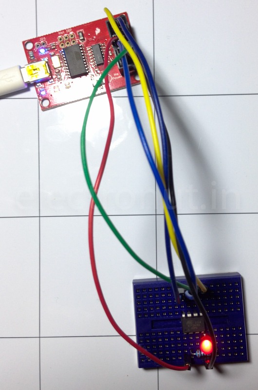
Now, we need to hook up our programmer to this chip. The connections you need for programming are VCC, GND, MISO, MOSI, SCK and RESET. These are clearly marked on the programmer, and from the above diagram, you know the corresponding pin on the chip. The programmer connects to your computer via the USB port. (Follow the instructions that came with the programmer to install drivers, etc.). One thing to note is that you are powering the chip using VCC from the programmer – so make sure that you enable that power switch on the programmer, if yours has one. Hook up a 100 Ohm resistor and an LED to PB3 (pin 2) of the ATtiny85. This is what my setup looks like.

Next, you need some tools to program the chip. There are many ways of doing this, but I use AVRDude. This will help you compile your code, generate the hex file, and flash it into the chip.
Now it’s time to write some C code. The program below toggles PB3 on the chip on and off, making the LED blink.
// main.c
//
// A simple blinky program for ATtiny85
// Connect red LED at pin 2 (PB3)
//
// electronut.in

#include <avr/io.h>
#include <util/delay.h>


int main (void)
{
  // set PB3 to be output
	DDRB = 0b00001000;
  while (1) {

    // flash# 1:
    // set PB3 high
    PORTB = 0b00001000;
    _delay_ms(20);
    // set PB3 low
    PORTB = 0b00000000;
    _delay_ms(20);

    // flash# 2:
    // set PB3 high
    PORTB = 0b00001000;
    _delay_ms(200);
    // set PB3 low
    PORTB = 0b00000000;
    _delay_ms(200);
  }

  return 1;
}
Next, you need a Makefile to do the magic of building your code. Here is a Makefile I modified from the one generated by CrossPack.
https://gist.github.com/electronut/8a4c297213620958ebef
This is how you program the chip from the command line:
$make install
You’ll get a flurry of messages from AVRDude, and then if it all works, you will see a happy blinking LED. 😉
Now you can remove the programmer, and by supplying 3V to VCC and GND pins, it will still work (as it should!).

I know this is short, but it should get you started. This is a vast topic, and if you want to go beyond blinking an LED, some research and tinkering is unavoidable. But these chips are amazing and can do a lot – so experiment, and have fun! 🙂
Some useful resources for AVR Programming
Adafruit Tutorial:
http://www.ladyada.net/learn/avr/avrdude.html
Hackaday Tutorial:
http://hackaday.com/2010/10/23/avr-programming-introduction/
Note for Windows Users
The above notes are for OS X, which translates easily for Linux and variants. If you are a Windows user, I recommend that you download MSYS, a collection of GNU utilities which will give you many of the nice Unixy command line utilities like sh, gmake, grep, etc.


