
I have a couple of servos on a pan/tilt bracket that I want to control from my Raspberry Pi. As I started looking at options, I read about the Adafruit 16-channel servo driver. This board is not available where I live, and I got curious about chips that generate PWM signals that could be configured via the I2C protocol. I found a cheap one (less than 2 USD) on element14 - the CAT9532 16-bit Programmable LED Dimmer chip from Catalyst Semiconductor.
This is a short post on communicating with the CAT9532 from a Raspberry Pi using Python and the smbus module.
I won't go into I2C - this is a very popular protocol, and you can read this excellent introduction here.
smbus is the module used on Raspberry Pi to communicate with I2C devices. If you are used to sending I2C commands like START/STOP/RESTART etc., you will find smbus to be very frustrating (like I did). The commands are at a higher level, and a typical I2C sequence is "baked in", which may or may not suite you. One particular known problem with smbus on Raspberry Pi is that it cannot send a "REPEATED START" I2C command - what this means is that you cannot communicate with popular accelerometer chips like Freescale MMA8452 which require a REPEATED START to read back data from its registers. I burned my fingers on this, trying it with another accelerometer chip, the Freescale MMA7660. You can read more about this issue here, for instance. The suggested workaround is to use software I2C (bit-banging).
But luckily, the CAT9532 does not use a REPEATED START, which means we can use Python + smbus to communicate with it.
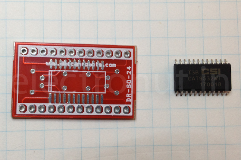
Looking at the datasheet, the CAT9532 has 10 registers, 2 read-only and 9 read/write, which can be used to set the frequency, duty cycle, and on/off state of 16 LED pins. The base address of the chip is 0x60, but you can use 3 more pins (3 more bits) to modify it.
This is what the chip looks like in its SOIC-24 package. I used a DIP adapter PCB so I could use it on a breadboard.
My goals here are:
- Make LED 8 (green) blink at 3 Hz, at 50% duty cycle.
- Make LED 7 (blue) "pulse" - going from off to on and back to off slowly.
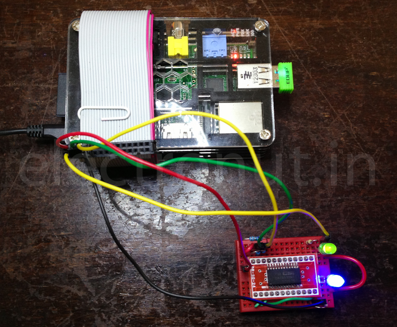
This is how I connected the hardware:
- A0, A1 and A2 pins (configurable part of device I2C address) are all connected to GND, as is pin VSS.
- Pull-up resistors of 4.7k for SDA, SCL and RESET pins of CAT9532 to +3.3V GPIO pin on Pi.
- Connect SDA/SCL from Pi to that of CAT9532.
- LED7 pin to 270 ohms to Blue LED(-), LED(+) to +5V on Pi.
- LED8 pin to 270 ohms to Green LED(-), LED(+) to +5V on Pi.
This is what the full setup looks like:
The full Python source is below. Run it from the Pi as:
sudo python rpi-cat9532.py
Now that I understand how to set the PWM frequency and duty cycle via I2C, I'll need to figure out how to drive servos with this output - probably use some MOSFETs. But that's for another post.