
I am feeling a little nostalgic. So I rebuilt one of the first circuits I put together when I started messing around with circuits in eighth grade. It's a very simple beginner project, and might appeal to your child - real or inner!
Another reason I wanted to put this up is because most "blinky" circuits I see now are based on the venerable 555 IC. This is fine, but the two transistor circuit is simpler for a beginner to understand than the innards of the 555, I think.
Here is the circuit. It's a two transistor astable multivibrator. (Read the wikipedia link for the gory details of how it works. ;-) )
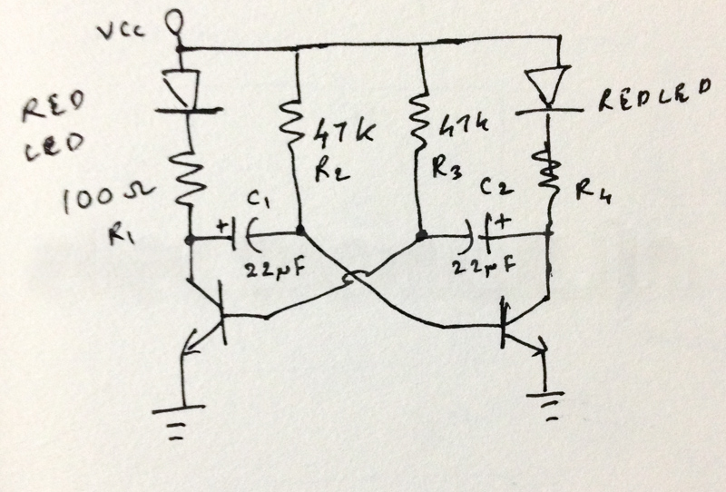
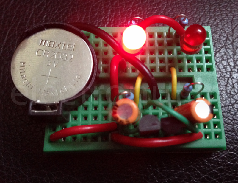
For supply, I used a 3V CR 2032 coin cell. The transistors are 2N2222, but I think any NPN transistor would work in this case. The LEDs are Red, which have low turn-on voltage, and this is important, since we're using a coin cell here. The circuit was assembled on a breadboard.
Even for this simple circuit, some calculations are involved to get it right. The total period of oscillation is given by:
$$ T = t_{1} + t_{2} = \ln 2 R_{2}C_{1} + \ln 2 R_{3}C_{2} \approx 0.693(R_{2}C_{1} + R_{3}C_{2})$$
Choosing $$ R_{2} = R_{3} = 47 K\Omega$$ and $$ C_{1} = C_{2} = 22 uF $$ gives us a total period of about 1.4 seconds - 0.7 seconds per LED. Good enough.
Now, to compute $$ R_{1} = R_{4}$$. Assuming a 0.6 V drop across the transistor, and a 20 mA current through the LED gives us $$ R = \frac{3 - 0.6}{20 mA} = 120 \Omega$$. So a 100 Ohm resistor, which is more common, will do just fine.
And here's the circuit in action:
Build it for your child! :-)