ATmega168 Power Save Mode and Pin Change Interrupt


Most times your microcontroller is running in a loop, waiting for something to happen – like a button press. All this while it is consuming power, and this could be an issue, especially if you are running the circuit from a battery. To counter this problem, there are ways of reducing the power consumption of your chip. Here are the various “sleep modes” supported by the ATmega168.


[Table reproduced from Atmel ATmega168 datasheet for illustrative purpose]


In a previous post about an Ambient Light sensor using an Op-Amp Comparator, I mentioned that we would be using the op-amp output to “wake up” an ATmega168. So here, we will be using the “power-save” mode from the above table, and use a pin-change interrupt to wake up from this sleep mode.


The setup used is shown below in the 2 schematics I had posted before. The output Vo from the op-amp should be connected to the pin 14 of the ATmega168 (PCINT0/PB0). Also, in this case, we are not using serial output, so you can remove the connections to the FTDI adapter.


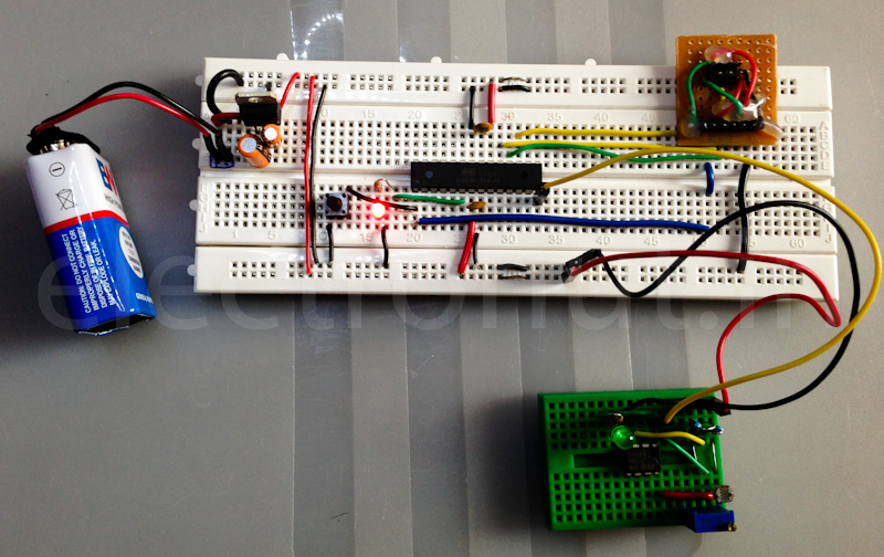
Here is what the circuit looks like, hooked up on a breadboard:


This is the how the program works:


  • When the program starts, start the 16-bit timer, set to fire an interrupt every 3 seconds. Start the timer only if pin 14 is low. (This means that the light level is high in our sensor circuit.).
  • When the chip is not sleeping, it will be flashing an LED attached to pin 6.
  • When the 16-bit timer interrupt happens, set a flag (a volatile variable) so that the main loop reads this flag and puts the chip to sleep mode. It will also turn the LED off at this point.
  • Set up a pin change interrupt on PCINT0 for any logical change in input. When the interrupt fires, if it was caused by a rising edge (ie., light to dark), wake up the chip, and stop the 16-bit timer. If the interrupt was caused by a falling edge (ie., dark to light), re-start the 16-bit timer.

You can read about pin-change interrupts and the 16-bit timer in the Atmel ATmega168 datasheet.


The complete code listing is below. The opening comments in the code also have all the required build commands.


//**********************************************************************
//
// Putting the ATmega168 into Power Save mode, and then waking it
// with a pin-change interrupt.
//
// electronut.in
//**********************************************************************

/*
build commands on OS X with CrossPack:
avr-gcc -Wall -Os -DF_CPU=8000000 -mmcu=atmega168 -c main.c -o main.o
avr-gcc -Wall -Os -DF_CPU=8000000 -mmcu=atmega168 -o main.elf main.o
rm -f main.hex
avr-objcopy -j .text -j .data -O ihex main.elf main.hex
avr-size --format=avr --mcu=atmega168 main.elf
avrdude -c usbtiny -p atmega168 -U flash:w:main.hex:i
avrdude -c usbtiny -p atmega168 -U lfuse:w:0xe2:m -U hfuse:w:0xdf:m -U efuse:w:0x01:m
*/

#include <avr/io.h>
#include
#include <util/delay.h>
#include <avr/interrupt.h>
#include <avr/sleep.h>

#define F_CPU 8000000

// for sleep
volatile int goToSleep = 0;

int main (void)
{
// Put an LED on PD4 (pin 6)
// PD4 as output
DDRD |= (1<<4);
//Set high
PORTD |= (1<<4);

//
// 16-bit timer setup:
//

// turn off interrupts
cli();

// 16 bit timer - every 3 seconds:

// Count cycles - 3*8000000/1024
OCR1A = 23437;
// Put Timer/Counter1 in CTC mode
TCCR1B |= 1<<WGM12;
// enable 16-bit timer interrupt
TIMSK1 |= 1<<OCIE1A;

// start 16-bit timer if PCINT0 pin-14 PB0 is low
if((!PINB & (1 << PB0))) {
TCCR1B |= (1<<CS12) | (1<<CS10); // Divide by 1024
}

// enable Pin change interrupt enable 0
// this is PCINT0 - pin 14
PCICR |= (1 << PCIE0);
PCMSK0 |= (1 << PCINT0);

// turn on interrupts
sei();

// loop
while (1) {

// delay
_delay_ms(100);
// toggle led pin on/off
PORTD ^= (1<<4);

// sleep section
if(goToSleep) {

// turn LED pin off
PORTD &= ~(1<<4);

// set sleep mode
set_sleep_mode(SLEEP_MODE_PWR_SAVE);
// disable global interrupts
cli();

// enable sleep flag
sleep_enable();

// enable global interrupts
sei();

// actually sleep
sleep_cpu();

// ...
// just awake here
// ...

// disable global interrupts
cli();

// enable Pin change interrupt enable 0
// this is PCINT0 - pin 14
PCICR |= (1 << PCIE0);
PCMSK0 |= (1 << PCINT0);

// unset sleep flag
goToSleep = 0;
// disable sleep flag
sleep_disable();

// enable global interrupts
sei();
}

}

return 1;
}

// pin change interrupt
ISR (PCINT0_vect)
{
// read PCINT0 (PB0 - pn 14):
if(PINB & (1 << PB0)) {

// rising edge

// disable sleep - wake up!
sleep_disable();

// stop clock for 16-bit timer
TCCR1B &= ~((1<<CS12) | (1<<CS11) | (1<<CS10));
}
else{
// falling edge

// clear counter in 16-bit timer
TCNT1 = 0;

// start 16-bit timer
TCCR1B |= (1<<CS12) | (1<<CS10);
}

}

// 16-bit timer CTC handler
ISR(TIMER1_COMPA_vect)
{
// set sleep flag
goToSleep = 1;
}